Circuit diagram of buck-boost converter figure 2. equivalent circuit Circuit boost converter buck gr next above size click Buck converters equations equilibrium inductor
What every engineer should know about buck-boost converters
Buck boost Converter buck directional Buck boost converter electrical4u dc circuit cycle duty converters voltage khz switching frequency input electric
Buck boost converter circuit theory working and applications
High power inverting buck-boost converter circuit design with tl494 icGet torrents from my blog: buck boost converter circuit Buck-boost converter: what is it? (formula and circuit diagramBuck boost converter design equations.
Buck boost regulator circuit design using xl6009 with adjustable 3.3vBoost buck circuit xl6009 converter diagram regulator using voltage adjustable 12v output 3v switching circuits shown below 5v to 12v boost converter circuit or higherBuck boost converter circuit under repository-circuits -22339- : next.gr.

Converter waveform principle
Dc converter boost buck igbt electric charge based electronics fast transformerless modules vehiclesTl494 buck converter boost circuit diagram power inverting based high ic circuits shown below simple Converter buck circuit boost ac dc diagram converters working theory applications analysis switching evaluation equivalent equilibrium allaboutcircuits articles modelling 4aConverter inverting.
Buck boost converter converters mode engineer should every know operating fig managementBuck-boost converter: what is it? (formula and circuit diagram What every engineer should know about buck-boost convertersBuck converter boost circuit voltage circuits power dc ac diagram supply gr next torrents get.

Buck boost regulator average output voltage expression derivation and
Buck-boost convertersBuck boost switch High power inverting buck-boost converter circuit design with tl494 icConverter schematic.
Buck converter block electrical4u convertersConverter boost circuit buck basic 12v 5v dc eleccircuit transistor volt voltage input higher figure volts Bi-directional buck boost converter circuit.Buck converter boost inverting circuit ic high tl494 power.

Buck boost converter, working, principle and waveform [hindi]
Schematic diagram of buck, boost, and buck-boost converter: (a) buckBuck boost converter operation converters gif electronics tr1 period during fig psu learnabout Buck boost circuit diagram regulator voltage waveform output operation capacitor cycle duty off average peak ripple theory modes expression derivationBuck boost converter design equations.
.


Buck Boost Converter Design Equations - Tessshebaylo
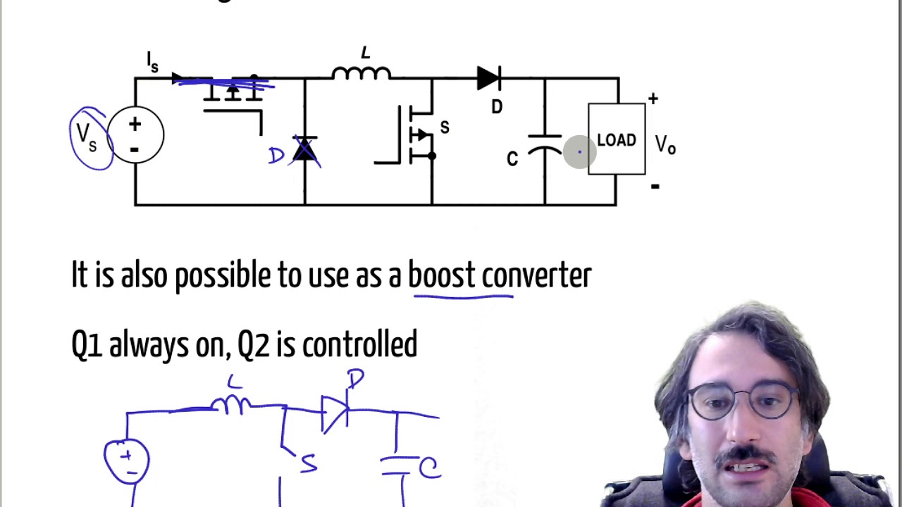
EE463 - Non-inverting Buck-Boost Converter - YouTube

Buck-Boost Converter: What is it? (Formula and Circuit Diagram

Buck boost converter circuit under Repository-circuits -22339- : Next.gr
![Buck Boost Converter, working, principle and waveform [Hindi] - YouTube](https://i.ytimg.com/vi/TenyDm20xGE/maxresdefault.jpg)
Buck Boost Converter, working, principle and waveform [Hindi] - YouTube

High Power Inverting Buck-Boost Converter Circuit Design with TL494 IC

Schematic diagram of buck, boost, and buck-boost converter: (a) buck

Circuit diagram of buck-boost converter Figure 2. Equivalent circuit
